Electronics wiring
Extension board
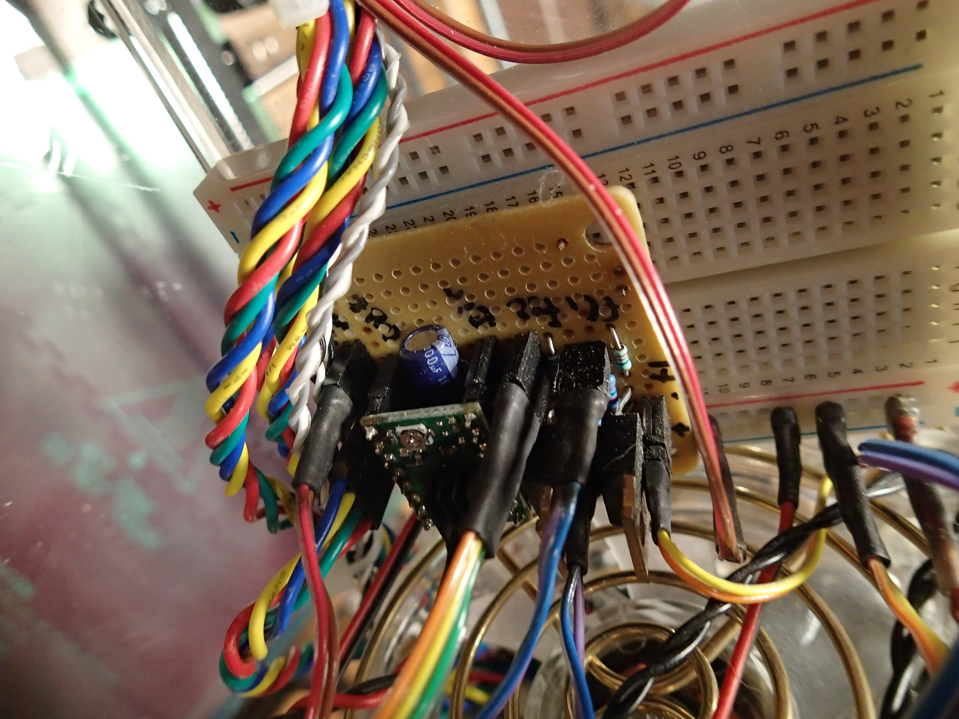
The board design presented here was done to allow mounting directly onto the breadboard RepRap X2 machines came with. The 16x16 prototyping board for soldering the schematic can be purchased in RadioShack. The components used are identical to those of RAMPS board. The MOSFETs are STP55NF06L.
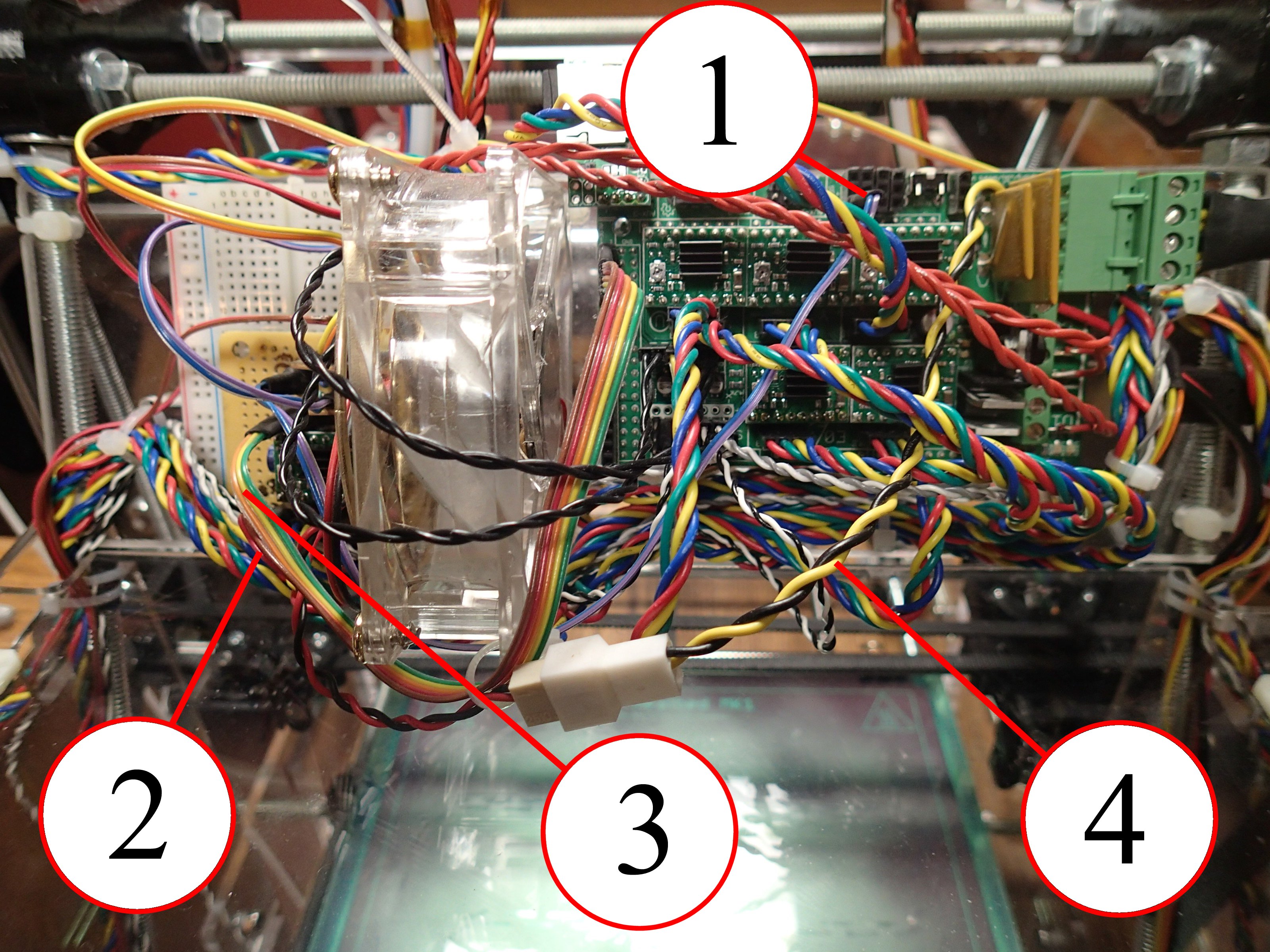
Hooking up to the RAMPS 1.4 board requires following (see picture on the right side of the page):
- Fan control signals from AUX-1, pins D0, D1
- 5V and GND from AUX-4
- Motor controls from AUX-4, pins D32, D47, D45
- 12V and GND (pins 3 and 4) of the power supply connector, feeds the extension board and all the fans connected directly to the breadboard.
https://reprap.org/wiki/RAMPS1.4
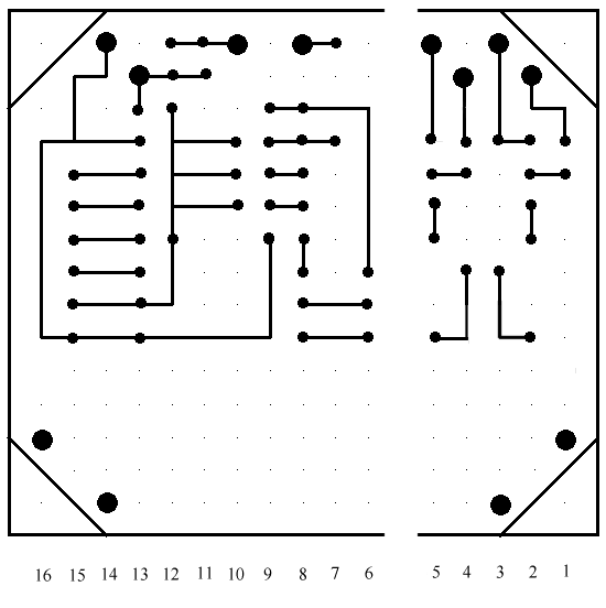
The schematics of the extension board is identical to that of the RAMPS "Stepper Drivers" and "Heaters & Fans" modules. The layout of the extension board can be seen by clicking on the top & bottom view images below. The big dots on the bottom view show the position of the pins that go into the breadboard. The top 2 rows should go into the power rails of the breadboard. The bottom 4 pins are not connected and used just for mounting.
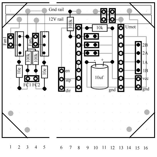
| Connectors | |
|---|---|
| Fan1 | Extruder 1 fan |
| Fan2 | Extruder 2 fan |
| FC1 | Fan1 control, from RAMPS AUX-1 pin D0 |
| FC2 | Fan2 control, from RAMPS AUX-1 pin D1 |
| en | Motor enable from RAMPS AUX-4 pin D45 |
| stp | Motor step from RAMPS AUX-4 pin D47 |
| dir | Motor direction from RAMPS AUX-4 pin D32 |
| vcc | +5V from AUX-4 pin 5V |
| gnd | Ground from AUX-4 pin GND |
| 1B,1A,2B,2A | Stepper motor connector |
| 2x8-pin connectors | A4988 Carrier (Pololu motor driver) |
| 3 jumpers (under Pololu) | Stepping control (the same as for RAMPS) |
| 2 12V power connectors | 12V main power, from RAMPS power in behind MFR500, 12V-AUX might work too |
The remaining connections are the same as for RepRap X2. The second hotend heater uses D9 and Thermistor 2 connectors. The X-Max enstop is required in order to home the second hotend X-carriage.