LCD Controller Support
LCD wiring
Connecting the Controller
Connect the Full Graphic Smart Controller to RepRap X2V3 RAMPS board and modify the configuration file using the standard reprap.org online instructions. When choosing how to do the wiring you can either try to use the connector dongle (usually the LCD controllers are sold with one) or make your own connector.
The dongle covers the whole RAMPS 1.4 AUX-4 connector, including the pins that are used by RepRap X2V3 extension board (5 pins on the side close to the AUX-3/SPI). You can try to either cut off that part of the dongle connector or use it for wiring the extension board as well.
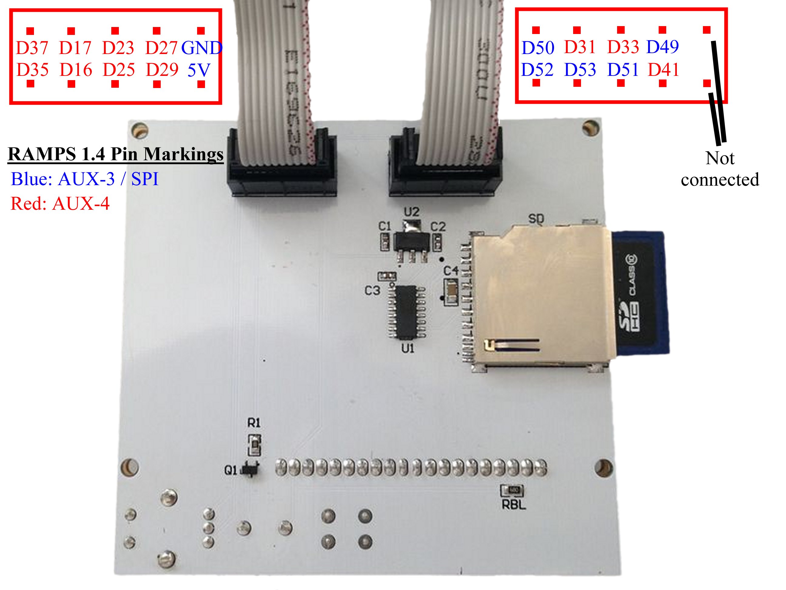
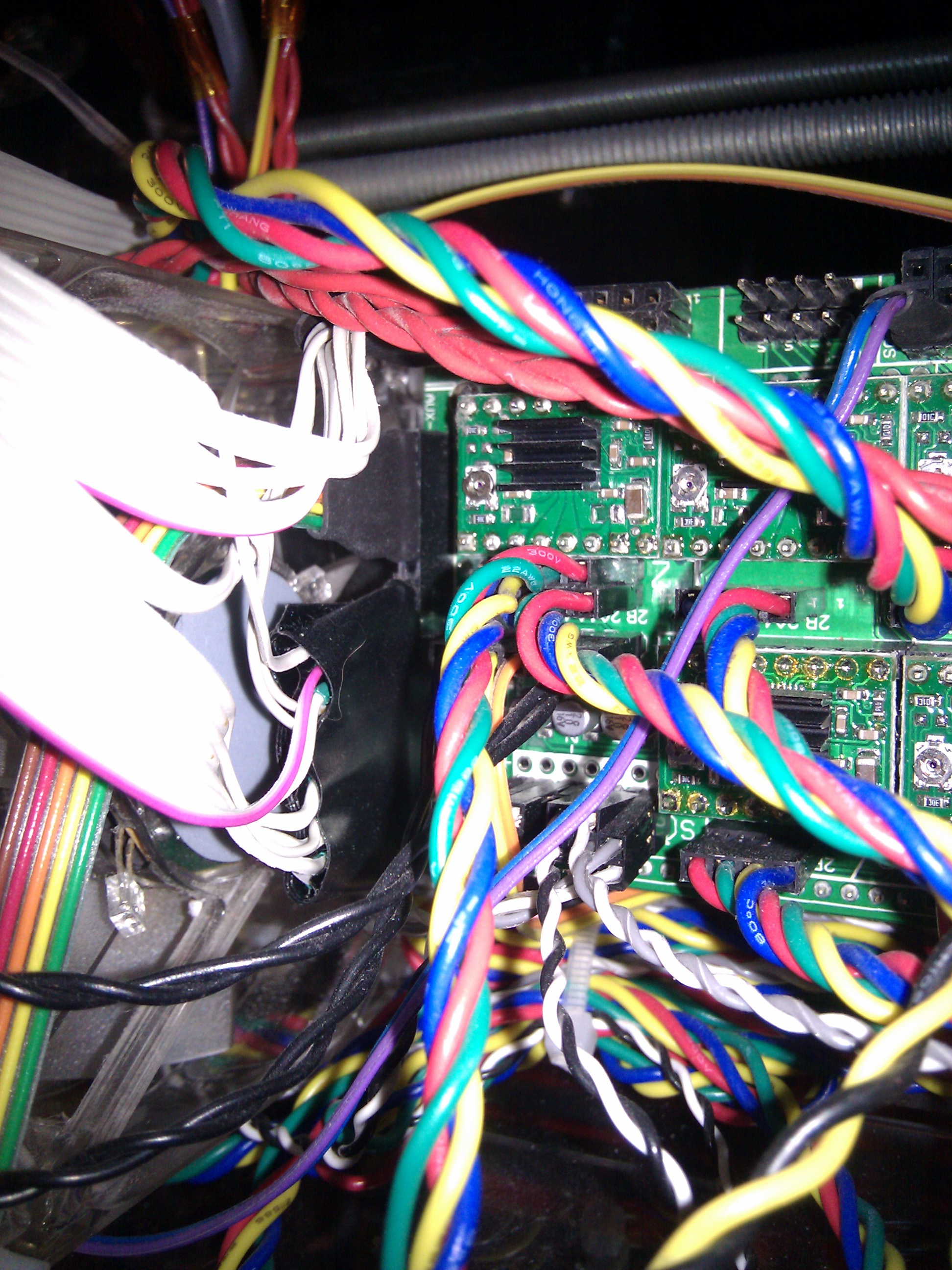
Alternatively you can just make your own connector. The "LCD Wiring" picture on the right shows where on the RAMPS 1.4 board to connect the pins from the LCD controller. Note that you will need approximately 17" (400mm) long wires to reach the RAMPS board on the back of the machine and neatly tie everything down.
Casing
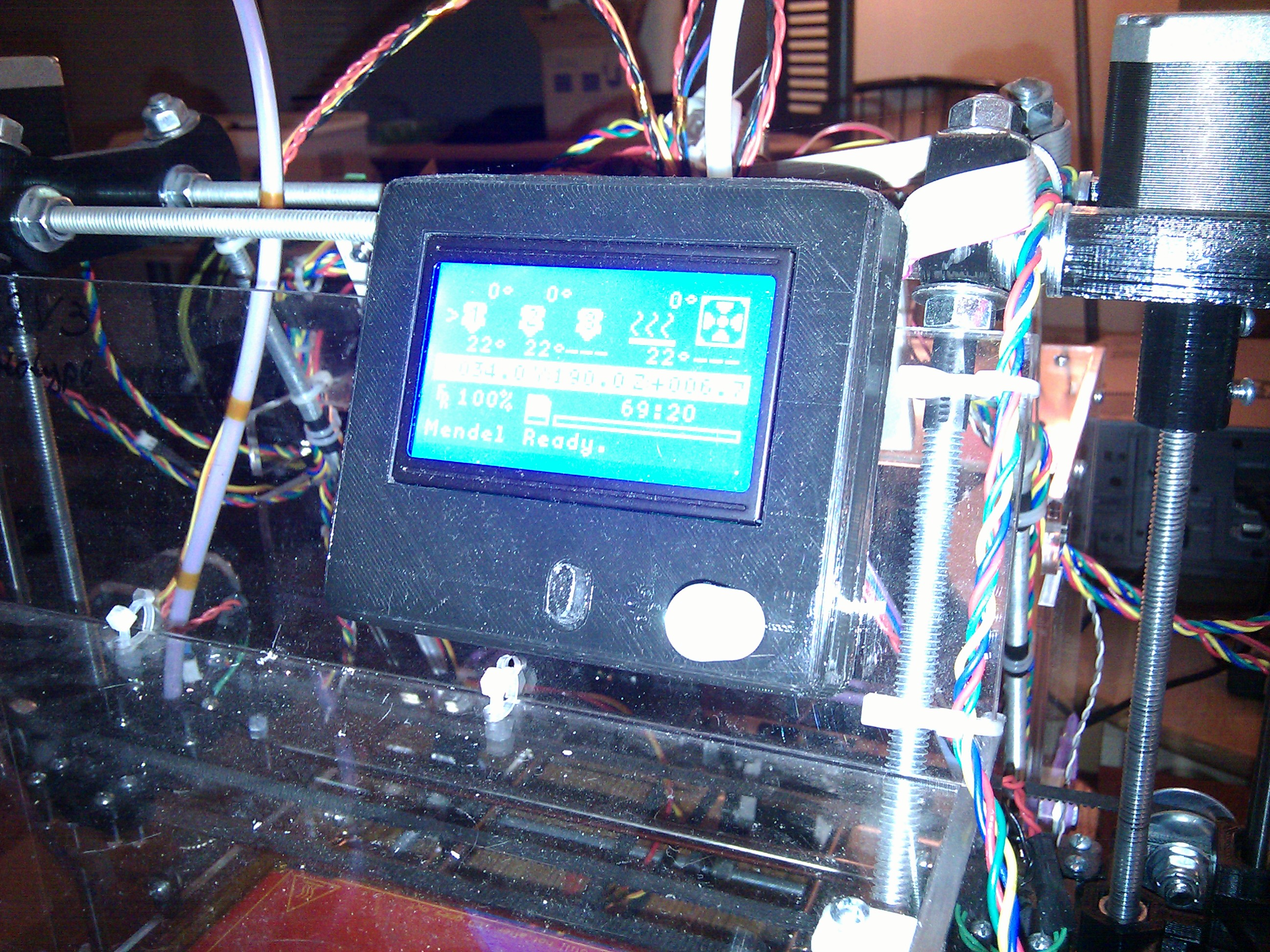
The LCD controller casing is made using Thingiverse thing 213852 design files. There's no need for any special brackets. The bottom panel is screwed directly to RepRap X2V3 acrylic casing faceplate using a couple 4-40x1 screws.
Usage
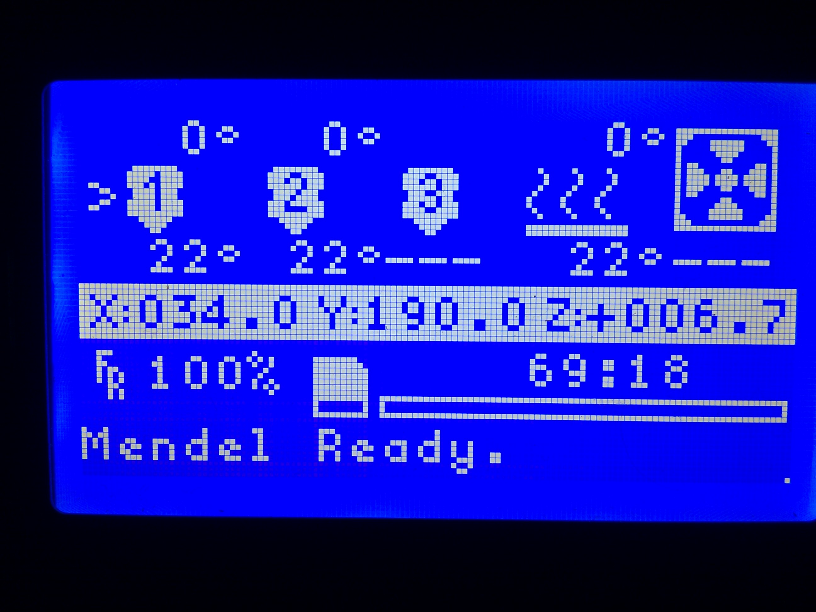
The status screen shows active extruder using ">" marker. The fan speed and coordinates are shown for the active extruder only. The status message line at the bottom shows buffer fill percentage. The changes are triggered when fill percentage crosses 25%/50% or reaches 100% boundary. If everything works correctly you should see buffer being 100% full while printing.
The configuration menus list extruders as 1 and 2 (i.e. not 0-based numbering). The compression compensation (if enabled) tables are configured row-by-row from lowest speed compensation to highest. You can configure up to the number of rows listed in the configuration file. Setting compensation speed to 0 indicates the last row (for table shorter than the max size).