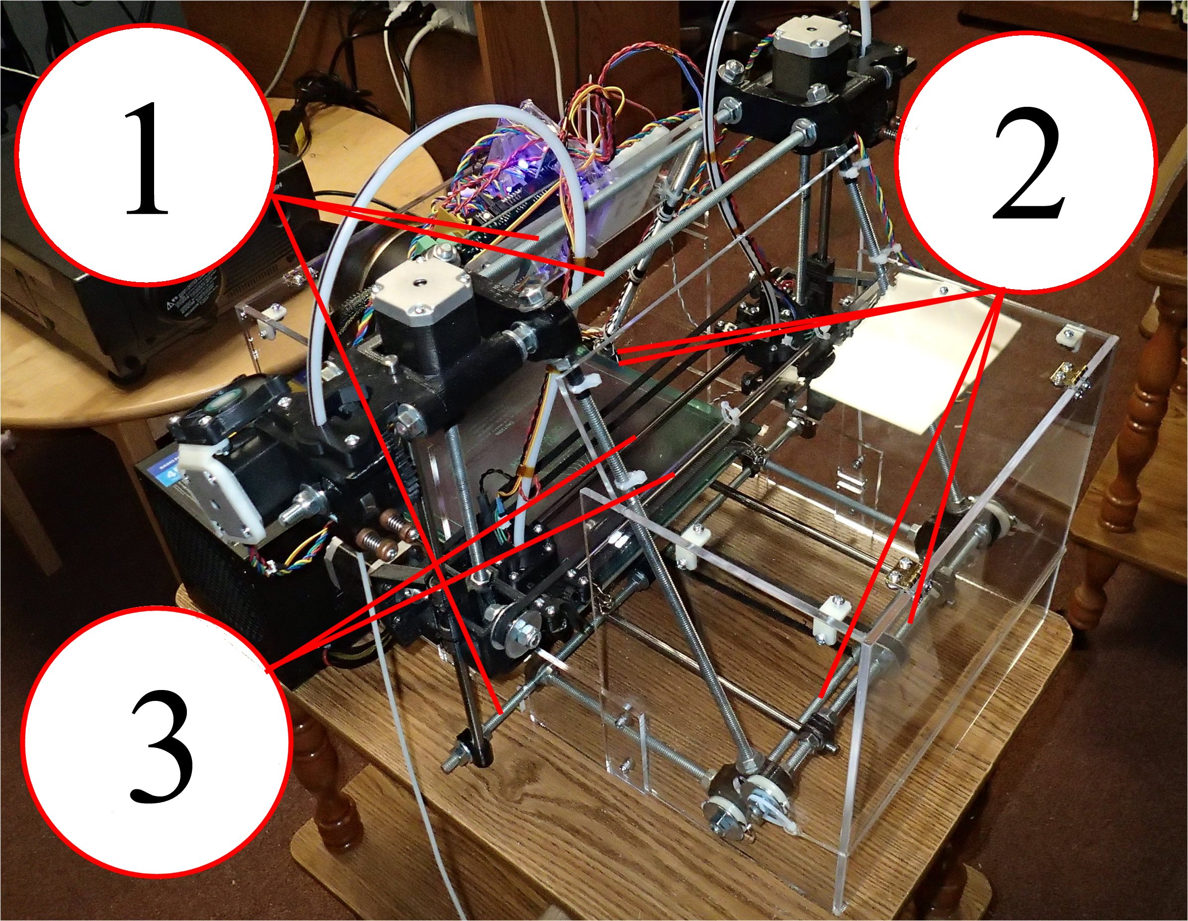
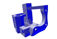
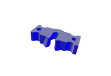
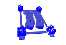
Location of Changed Rods
The hardware design is similar to RepRap X2 (that is based on SAE Prusa's Mendel), but X2V3 has to be slightly
wider and therefore requires some of the metal rods to be longer (basically all the rods that are positioned horizontally).
Below is the list of the changed rod lengths. Both, the original (RepRap X2 or Prusa's Mendel)
and correspondent X2V3 rod lengths are listed.
- Two threaded rods on top and one at the bottom of the machine that are used for mounting Z-motors, extruders
and clamp the lower end of the vertical smooth rods:
3x440mm (original) -> 3x465mm (X2V3)
- Four threaded rods for connecting the frame triangles at the bottom front and back of the machine:
4x294mm (original) -> 4x320mm (X2V3)
- Two smooth rods the hotend carriages slide on:
2x392mm (original) -> 2x410mm (X2V3)

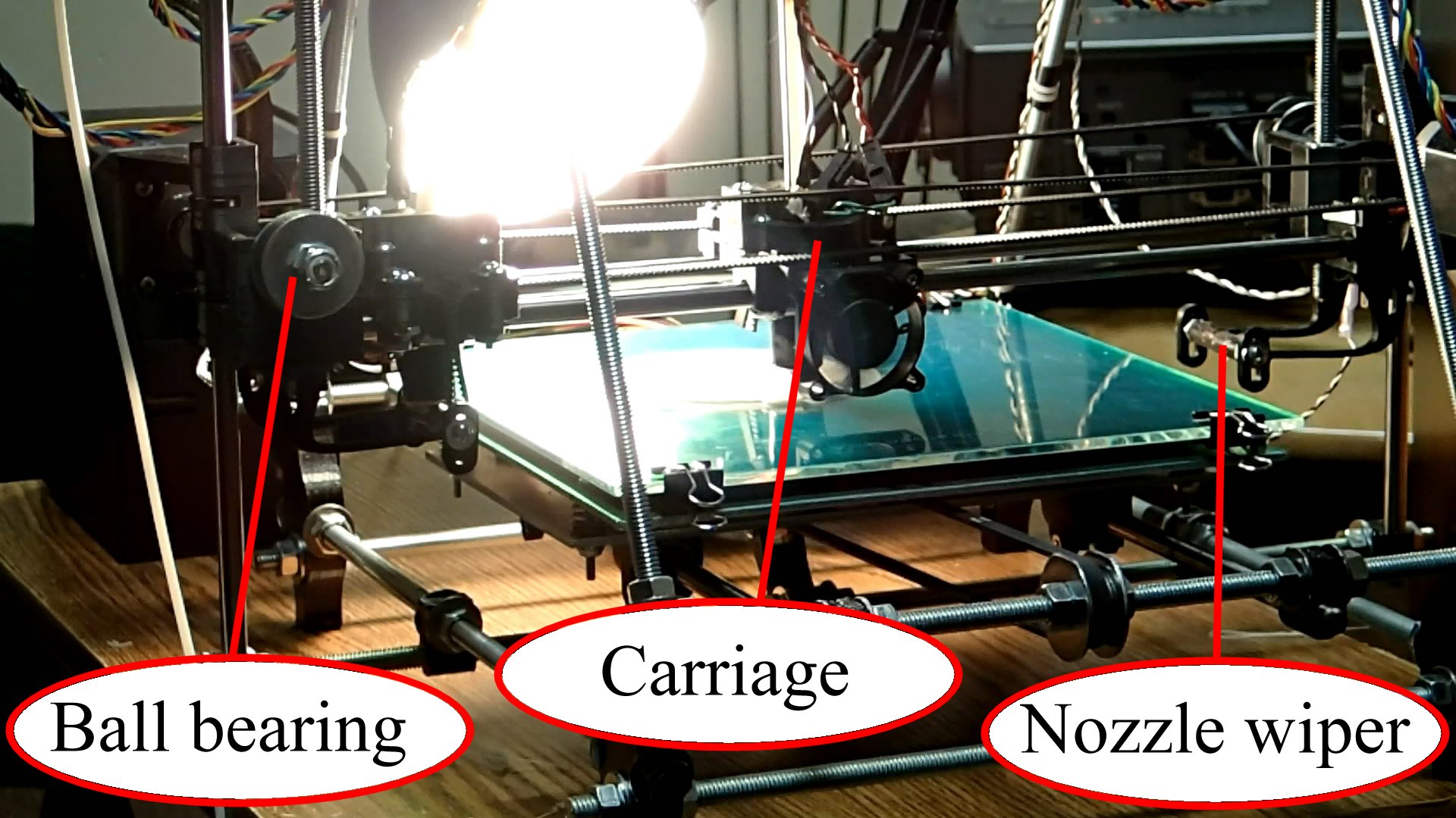
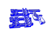
Additional parts
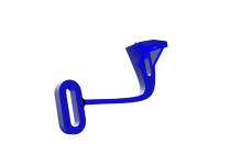
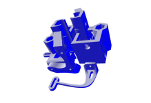
The additional parts for making the second hotend carriage and its driving mechanism are:
- one timing belt and one pulley;
- one ball bearing (to loop the belt over);
- two fender washers (for keeping the belt on the ball bearing);
- 40-50mm piece of threaded rod (for mounting the ball bearing);
- 3 linear bearings (for the carriage).
A few more of various nuts and bolts will be needed. For the carriage assembly those are 3/4" and 1" long
6/32" machine screws and nuts (can be purchased in HD or Lowe's hardware stores). A few 5/16 washers
and two locking nuts will be needed for the ball bearing mounting. You'll also need more of the smaller screws
for mounting the motor and attaching the 40mm fan to the carriage.
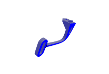
The nozzle wipers can be made using various techniques and materials. I'm using about 40mm long piece of
a thick silicone tube with a triangular cut up to the center of it where the nozzle slides over it
(right in the middle). The 3/4" long 6/32" screws are tightened on each side of the wiper arms and the
tube goes onto the screws (it sits tight enough to prevent it from rotating).
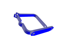
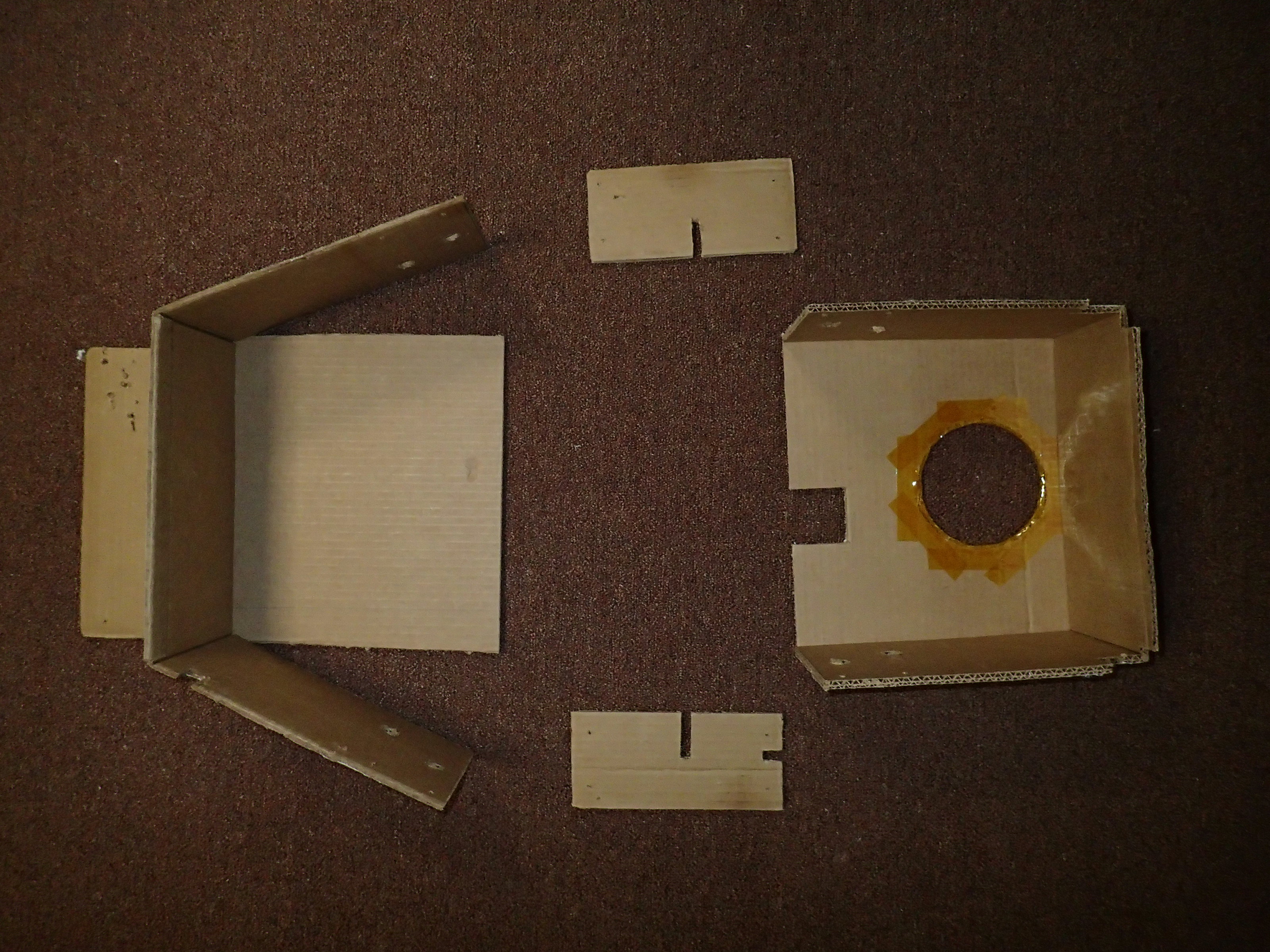
Cardboard case
The case covers most of the printing area preventing uncontrolled drafts that cool down the build
plate and the part being printed. That helps to improve consistency of the prints, significantly
speeds up heating of the build plate during startup and decreases warping.
The easiest way to see how useful it can be is to cut it from the coagulated cardboard.
That might even work fine as a permanent solution (ignoring potential fire hazard problem).
When time comes to switch to a different material, the cardboard case can be used to adjust design for
better fitting as all the RepRap machines end up being a bit different.
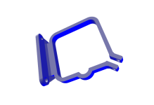
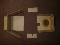
The picture (at the right side) shows the cardboard case that was used as the template for
the design files to cut the acrylic plates for making the casing of the RepRap X2V3 machine
pictured on the top of the page. The ends of the threaded rods protruding from the sides of
the machine frame legs go into holes on the sides of the casing. The casing is also attached to
the frame on the top (similarly to the electronics mounting plate). The front and back of the casing
are connected using the small side plates. The front door plate is hinged (using packaging tape in the
cardboard case). The back plate has circular hole for the heat lamp.
Design files for laser cutting the casing plates:
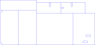
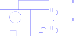
Those SVG files can be used with
ponoko.com
laser cutting service. The clear 4.5mm thick acrylic was used for my machine casing.
Note: the holes for connecting the plates are not a part of the design and have to be drilled manually
or added to the design files depending on the kind of brackets and hinges used.
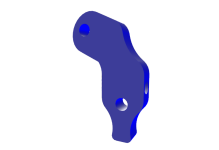
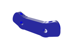
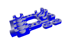
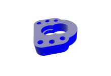
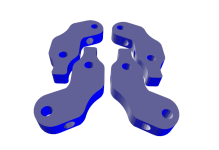
Plastic parts:
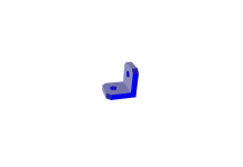

The above plastic parts might come useful for assembling the casing. The leftmost is a bracket
for connecting the plates. The rightmost is a special plastic washer. Those plastic washers are placed
over the 5/16 nuts on the side of the machine legs. The flat surface should face the washer under the nut.
The case side plates then go on top of those and tightened using big metal fender washer and
another 5/16 nut. The plastic washers (by bending) give some room to adjust the position of the casing
side plates.